Post
Teaching Steel Industry Equipment to See
A practical look at how AI, computer vision, and deterministic geometry can work together to turn messy real-world perception into reliable measurements a machine can actually use.
Measuring Reflective Surfaces with Stereo Vision
 Ali MaghamiSina Alborzi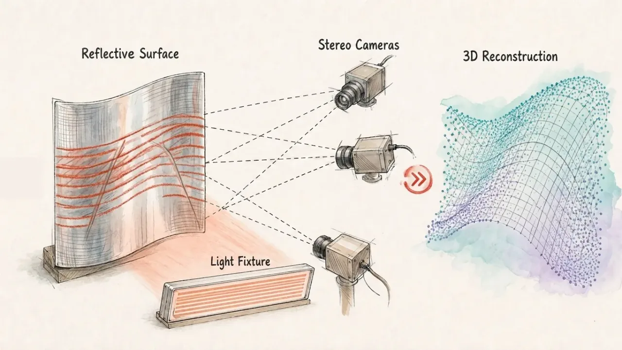
Images are AI-generated and used for illustrative purposes, as permission to publish original project imagery was not available.
Reflective materials are notoriously difficult for computer vision. Glare can hide texture, wash out edges, and make conventional illumination unreliable.
This project began with the opposite idea: what if the reflection is the signal?
Instead of trying to see the surface directly, the system observes the reflection of a known light pattern. When the surface moves, tilts, or curves, that pattern changes in predictable ways. Multiple synchronized cameras see those changes from different viewpoints and use stereo geometry to reconstruct the surface in 3D.
The result is a non-contact machine-vision system that can measure a moving reflective sheet while the cameras and computing hardware remain at a practical distance.
Recovering 3D points is only part of the problem. Measurements must also remain meaningful when nearby equipment shifts or tilts.
To handle this, the cameras track reference markers fixed to the light fixture. Those markers define a local coordinate system that is recalculated with every measurement. Surface position, orientation, and shape are therefore reported relative to the equipment—not just relative to the cameras.
This small architectural decision makes the system much more useful in the field. It separates real surface movement from changes in the measurement setup.
The reconstructed surface supports several measurements at once:
Together, these outputs turn camera images into spatial information that another automation or control system can use. That is the connection to Physical AI: reliable perception becomes a practical input for decisions and action in the physical world.
The project was designed for a demanding production environment, so the hardware layout mattered as much as the vision code.
The light pattern—the simpler and more robust part of the setup—was placed near the surface. The cameras, optics, electronics, and processing computer were kept farther away. Three synchronized cameras provided overlapping viewpoints and redundancy, while a low-latency data link carried images to an industrial computer for real-time processing.
This separation reduced exposure of sensitive components and made the system easier to maintain. It also demonstrates a lesson that applies well beyond this project: a strong computer-vision solution is a complete system, not only an image-processing model.
The system was tested continuously for two months on a production line with moving reflective sheets up to 72 inches wide. Surface finish and operating conditions changed during the trial, but the line pattern remained detectable and the system continued to track edges, movement, and curvature.
Two comparisons helped validate the measurements:
The trial also exposed the practical limits. Clear optical access and clean protective windows remain important for long-term operation. Even so, maintenance during the pilot was minimal, and changing reflectivity did not prevent reliable feature detection.
This work reframes a familiar machine-vision problem. A shiny surface does not have to be an obstacle; with the right optical setup, its reflections can carry rich geometric information.
More broadly, the project brings together several areas I care about: computer vision, stereo vision, 3D reconstruction, real-time software, systems architecture, and intelligent automation. The interesting part is not any one algorithm. It is how optics, geometry, hardware, and software work together to turn a difficult measurement problem into a system that can operate in the field.
The next steps are longer-duration trials, improved measurement sensitivity, and tighter integration with automated control. The same principle may also extend to other reflective materials and applications where direct contact is undesirable or conventional sensing is difficult.
Patent: Vision method and system for coating processes and systems — WO2026039905A1 (opens in a new tab)
Related work: Vision-Based Non-Contact Measurement of Strip Deformation and Position in Continuous Galvanizing Lines (technical paper and presentation, 2026).