Post
Teaching Steel Industry Equipment to See
A practical look at how AI, computer vision, and deterministic geometry can work together to turn messy real-world perception into reliable measurements a machine can actually use.
A stereo-vision system for measuring robot pose and correcting positioning errors online through visual feedback.
 Ali Maghami
This research developed a stereo-vision system for high-precision robot pose measurement and online error correction.
The system independently measured the robot tool and a reference fixture, estimated their relative 6D pose, and used that measurement to correct robot motion.
A robotic drilling setup was used for validation, but the core work focused on stereo vision, 3D localization, pose estimation, calibration, and closed-loop robot control.
The system used two synchronized cameras to track passive optical targets attached to the robot and reference fixture.
The vision pipeline:
The resulting measurement provided the robot’s full 6D pose:
X, Y, Z + Roll, Pitch, Yaw
Several target-localization methods were evaluated, including centroiding and ellipse-fitting approaches using edge and gradient information.
Gradient-based methods achieved the highest accuracy, while centroiding provided significantly faster computation with competitive performance once practical calibration errors were considered.
The cameras, robot base, robot flange, tool, and reference fixture each operate in different coordinate frames.
The project therefore included calibration and rigid-body transformation estimation between the vision system and robot.
Robot poses and simultaneous vision measurements were used to solve these transformations and convert vision-measured errors into robot motion commands.
The complete pipeline was:
Stereo Vision → 3D Tracking → 6D Pose → Relative Pose Error → Robot Motion Correction
Vision measurements were used directly as feedback for robot positioning.
The system compared the measured relative pose with the desired pose, calculated the 6D error, transformed it into the robot coordinate system, and generated corrective motion.
Two correction strategies were implemented:
This turned the vision system from a measurement tool into part of the robot control loop.
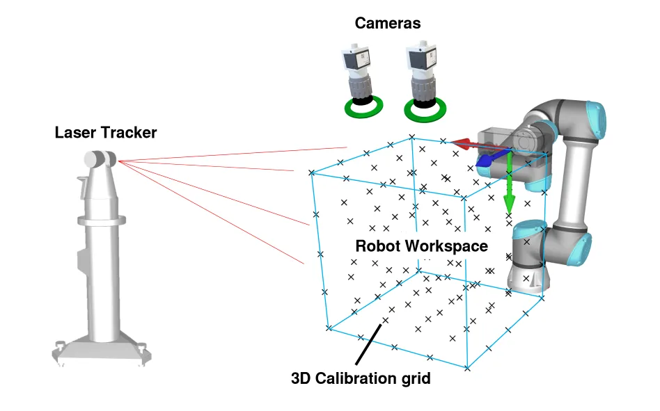
The vision system was validated against a high-precision laser tracker.
The best target-localization methods achieved mean 3D distance errors of approximately:
For robot correction, initial positional errors of approximately 1 mm were reduced to below 0.1 mm in two iterative correction steps.
The closed-loop system was also tested with simultaneous translational and rotational errors, demonstrating online 6D pose correction using visual feedback.
The project included:
The central engineering problem was converting small image-space measurements into sufficiently accurate physical pose estimates and robot motion corrections.
This project demonstrated computer vision as more than object detection.
Here, vision was used for measurement, localization, state estimation, and closed-loop control.
The system independently measured where the robot was relative to its task and used that information to correct its motion in real time.
Vision became part of the robot’s feedback loop.